Have questions? Get in touch with our experts.
Connect with our expert team via email or phone.
1-800-890-7593customerservice@emotorsdirect.ca


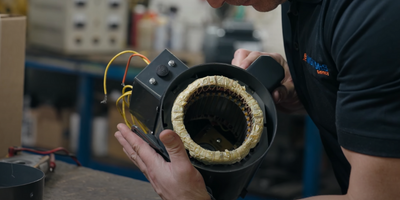
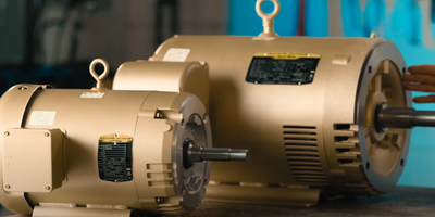
Rely on the eMotors Direct team of experts for your next custom motor project
Categories
Brake Motor Class 1 Division 2 Motors Coolant Pump Crusher Duty DC Motor Definite Purpose Dual Rated 50Hz/60Hz Explosion Proof Farm Duty Furnace Motor Gearmotors General Purpose AC Motors Generators Grinder IEC Metric Motors Integrated Drive Motors Inverter/Vector Duty Oilwell Permanent Magnet AC Pump Motors Reel Motor Severe Duty IEEE 841 Severe Duty Motors Single Phase Motors Three Phase Motors Two Speed Motor Vertical Shaft Motors Washdown Motors
September 9, 2025
Connect with our expert team via email or phone.
1-800-890-7593